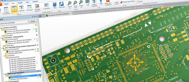

The import tool has been run and the work of verifying designators and symbols has been started. Note: There's already a start of the conversion. Find KiCAD library symbols/footprints and recreate missing ones. The work includes: Using the same designators and net names and making sure all parts are connected.

CAD routing is not necessary to do, since any future work will require the routing to be changed anyway. The CAD footprints, layout and outline will also be identical. The resulting KiCAD project will have identical schematics. It's a conventional four-layer PCB with two power planes. The attached BOM contains almost all components. The PCB also has two RGB LEDs, battery management, barometer, GPS module with active antenna detection, speaker and a few other features. The PCB has a MCU that receives data from two SPI radio modules and relays the data to USB, Ethernet and Bluetooth for further processing on a PC. Since we will do all future work in KiCAD, this project needs to be converted to KiCAD 6.0.


 0 kommentar(er)
